

|
PASSIVE SAMPLING |
|
Passive sampling tools provide an analytical measure of the the bioavailable fraction of site contaminants in pore water or surface water. Demonstrating the sequestration of contaminants and the reduction of bioavailability to benthic organisms and fish is the most important metric for demonstrating success in the AC remedy. Passive samplers may be deployed alone, or coupled with direct measures of bioaccumulation via in situ or ex situ bioassays. The utility of the passive sampler is in the ability to deploy large numbers of samplers across a site, and the ability to measure the contaminants below the AC, within and above the AC, as well as in the surface water above the site.
|
 Passive samplers deployed in sediments or water pick up contaminant molecules in similar fashion to bioaccumulation in benthic infauna, shellfish, or fish. Sampling materials can include LDPE, POM, and SPME (adapted from EPA and SERDP/ESTCP 2017). |
|
Passive samplers have been part of the long term monitoring programs at virtually all of the AC remedy sites to date. Passive sampling was first effectively demonstrated at the first field-scale demonstration of AC at the Hunters Point Annex in 2005. Other sites using passive samplers, and/or biological measures of contaminant sequestration are listed in the table below. |
| Site | Contaminant | Year Constructed | Passive and Biological Sampling Media | Project Web Link | |||||
| Low Density Polyethylene (LDPE) | Solid-Phase Micro-Extraction (SPME) | Polyoxy-methylene (POM) | Ex Situ Pore-water | Ex Situ Bioaccumu-lation | Benthic Infauna | ||||
| USN Hunters Point 2015 Pilot Study | PCBs | 2017 | ü | ü | ü | Hunters Point 2015 Demonstration Project | |||
| Activated Carbon Pilot Study, Lower Duwamish Waterway, Seattle, WA |
PCBs | 2017 | ü | ü | ü | LDWG Web Site | |||
| USN Sierra 1B Pier Pearl Harbor, HI |
PCBs & mercury | 2015 | ü | ü | ü | USN Sierra 1 B Case Study | |||
| Mirror Lake Restoration Dover DE |
PCBs | 2014 | ü | ü | Mirror Lake Case Study | ||||
| Puget Sound Naval Shipyard Bremerton, WA |
PCBs & mercury | 2012 | ü | ü | ü | ü | ü | PSNS Case Study | |
| Berry’s Creek, NJ | Mercury & PCBs | 2012 | ü | ü | ü | ü | EPA, 2013 | ||
| ESTCP ER-200835 | |||||||||
| Lower Duwamish Slip 4 Seattle, WA |
PCBs | 2011 | ü | Slip 4 Lower Duwamish | |||||
| Canal Creek, MD | PCBs & mercury | 2010 | ü | ü | ü | ü | ü | Canal Creek Case Study | |
| ESTCP ER-200835 | |||||||||
| Naval Air Station, Cottonwood Bay, Dallas TX |
PCBs, PAHs, chromium, lead | 2009 | ü | ü | ü | SERDP ER-1493 | |||
| NAVFAC TR-2366-ENV Technical Report | |||||||||
| Bailey Creek, Fort Eustice, VA | PCBs | 2009 | ü | ü | ü | Bailey Creek Case Study | |||
| Grasse River, Massena, NY | PCBs | 2006 | ü | ü | Grass River Pilot Project Web Site | ||||
| Hunters Point 2005 Pilot
Project San Francisco Bay, CA |
PCBs & PAHs | 2005 | ü | ü | ü | SERDP-1207 | |||
| ESTCP ER-200150 | |||||||||
| Hunters Point 2005 Case Study | |||||||||
| Abbreviations | |||||||||
| PAH - poycyclic aromatic hydrocarbons | |||||||||
| PCBs - polychlorinated biphenyles | |||||||||
|
Guidance Documents for Passive Sampling |
 |
|
Integrating Passive Sampling Methods into Management of Contaminated Sediment Site: A Guide for Department of Defense Remedial Project Managers provides remedial project managers guidance on how to integrate passive sampling into management of contaminated sediment sites, including AC remedy sites. Written as a companion document to the User’s Manual, the author team conducted extensive interviews with RPMs (DoD and EPA), scientists, analytical laboratories, and practitioners. The Guide focuses principally on passive sampling of hydrophobic organic compounds (e.g. PCBs, dioxin/furans, PAHs) using POM, PDMS or LDPE. Topics covered include what do passive samplers measure, how can they be used in remedial investigations feasibility studies or remediation, examples of use in the RI/FS and remediation process, a list of commercial laboratories that can do this work, and how to use the results in the decision-making process. |
 |
|
Practical guidance on using polyethylene or solid phase microextraction samplers may be found at the SERDP and ESTCP Bioavailability web site. Additional excellent on-line scientific publications on passive sampling include papers by Oen et al (2011), Ghosh et al (2014), and Greenberg et al (2014). Additional resources may be found at the bottom of this web page. |
|
Logistical Considerations |
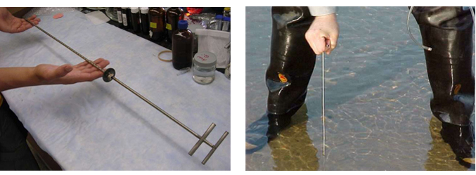
 Examples of Field-Deployed Passive Sampling Frames From Menzie et al 2016 (see Additional Resources below) |
|
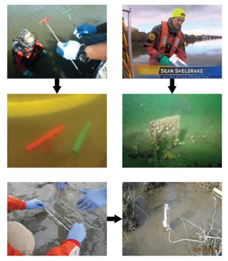
Sediment bed conditions, the type of sediment and presence of rip rap or other debris on the sediment surface need to be considered. Placing samplers into soft sediments is relatively easy, but having to push samplers through a sand layer or past surface debris may require coupling the sampler to a drive system. For example, at a site on the Lower Willamette River in Oregon the bedded sediment varied from soft silt/clays, to harder sands with cobble. A diver- operated impact hammer was needed here to drive in the samplers. Due to the abundance of glass, nails, cables, rocks, a sampling plate was attached during the drive, and then removed by the diver. |
 |
|
|
|
|
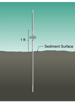
A pair of LDPE samplers being handed off to a USEPA diver on the Lower Duwamish Waterway at Seattle, WA. For these samplers, the diver inserts the frame up to the white tape to leave 10 cm sticking up out of the bed and 40 cm of PE penetrating down into the sediment. Gschwend et al 2013. Obtaining Measures of Freely-Dissolved Polychlorinated Biphenyls (PCBs) in Pore Water of the Lower Duwamish Waterway (LDW) Sediments Using Passive Polyethylene Samplers |
Surface water SPME samplers were deployed 1 ft above the sediment surface by attaching them to the top of an inserted sampler (Figure from Thomas et al. 2012) |
|
|
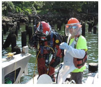
 An extreme end of logistical considerations for passive sampling are illustrated at site located within the Lower Willamette River Superfund Site in Portland, OR. The nearshore area had docks and old pilings, which necessitated the use of commercial divers to safely install and retrieve the samplers. LDPE was
 selected as the sampling media, and the frames used were the same as those originally developed by Massachusetts Institute of Technology. Vibracores previously collected showed that the sediment varied from soft silt/clays, to harder sands with cobble. The surface of the sediment was strewn with wood debris, glass, nails, cables, and rocks. The site is an active berthing area with large ships and tugs generating wake and propeller wash.
|
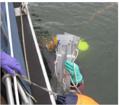
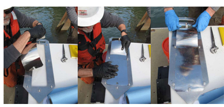
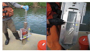
Surface floats could not be used in these active shipping lanes. The passive samplers had to be driven into the hard, compacted sediment bed. A diver- operated impact hammer was made to fit the passive sampling frame and included the hammer assembly (A), a plate cover to protect the LDPE during the drive (B), and a fixed depth-stop (C) to ensure consistent depth-of- placement of the LDPE. The LPDE was fit into the sampling frame at the laboratory; the cover plate was placed in the field and the entire assembly handed to the diver. Prior to the dive, the sampling location was located with GPS and fixed with an anchor. |
|
The diver descended with the assemble down the rope to the anchor, drove the assembly into the sediment. To ensure that the samplers were not lost to propeller wash, screw anchors were placed upstream/downstream of the samplers, and the sampler frame fixed with rope to the screw anchors. An acoustic pinger was then cable-tied to the frame for later relocation. The last step was to remove the cover plate from the sampler.
|
|
|

|
|
|||
|
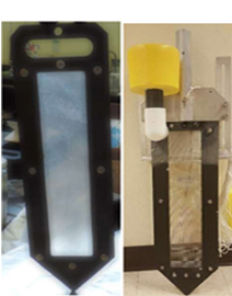
Universal Sampling Frame
|
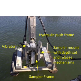
Power Deployment System
|
Passive Push System
|
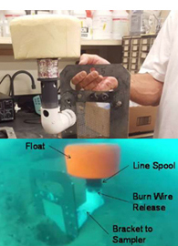
Time Release Floats
|
|
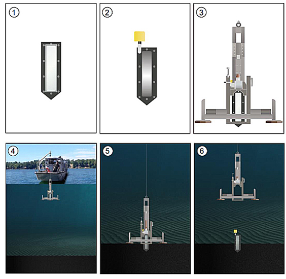
1
|
The passive sampling media (e.g. LDPE) is fixed on the sampler frame. Similar to the MIT samplers, the polyethylene (or other media) is fastened to the frame with exposure occuring in the frame window.
The retrieval system is fixed to the sampler frame.
|
|
|
Drive-Frame Deployment |
|
|
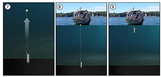
Time-Release Float Operation |
|
Webinars and Podcasts
|
